Impressions after three weeks
For three weeks now I have an Alfawise U50 at home. You can read the article about unboxing and assembly here.
So far I can say that the printer just works. I still print exclusively with Octoprint and that works fine, too. In this article I present which modifications or add-ons I have added so far and what I have learned about handling the printer.
Attachments
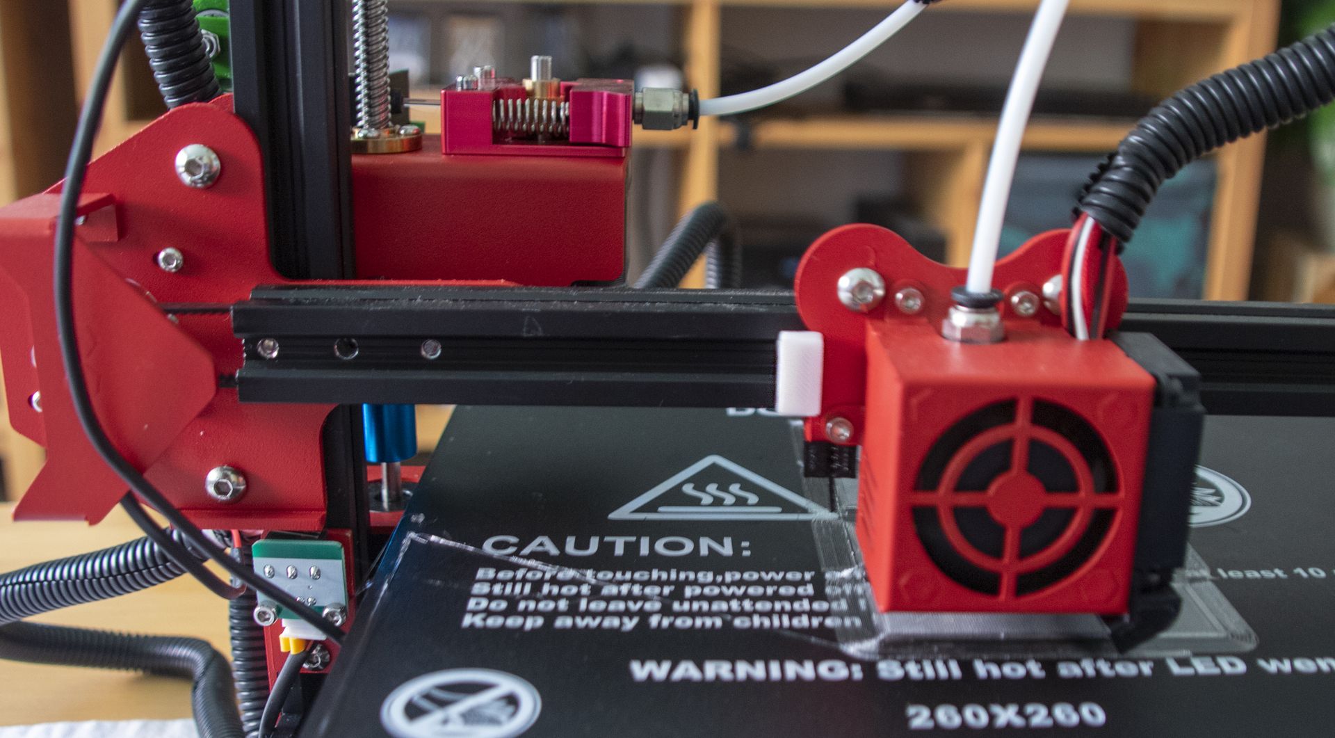
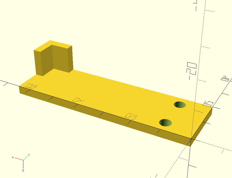
X-Axis Spacer
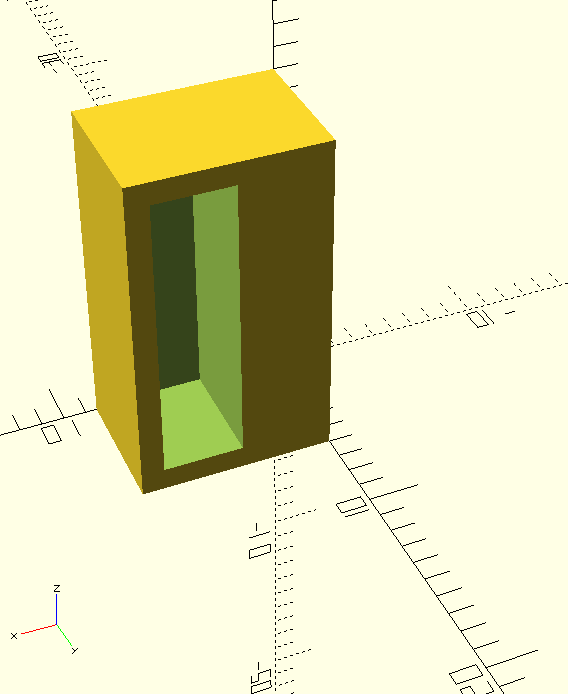
The first modification I printed is a spacer for the X-axis endstop. When delivered, the nozzle is outside the print bed when the endstop is pressed.
So I designed an adapter in OpenSCAD that can be plugged onto the existing metal tag and stops the nozzle 4mm further inside.
Camera Holder
The next attachment is a camera holder for a Logitech C270 webcam (Thingiverse).
I mounted the camera on top of the crossbar, so that I have the complete printing bed in the picture.
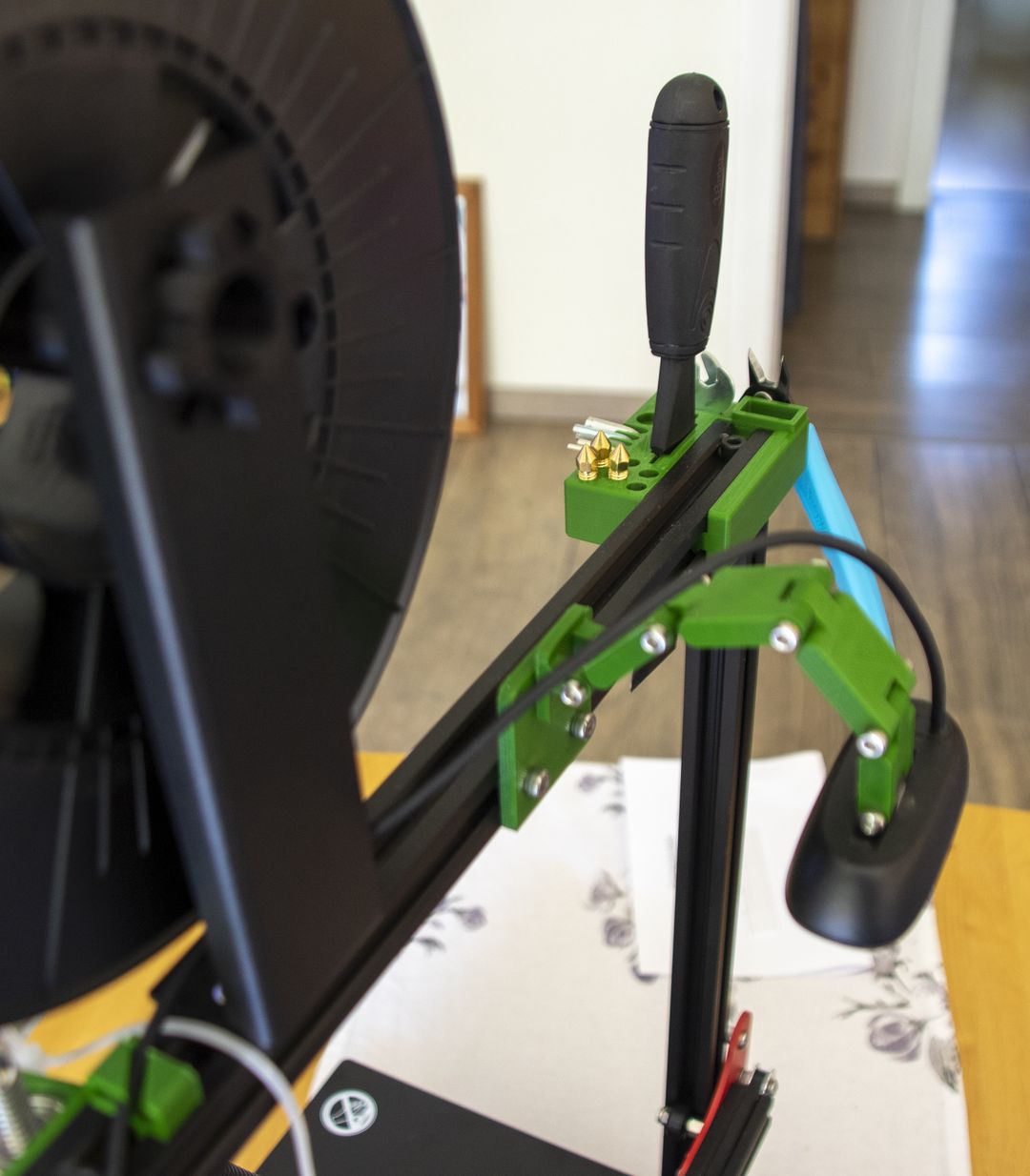
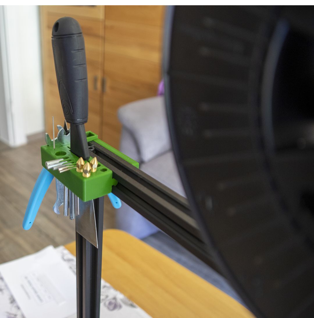
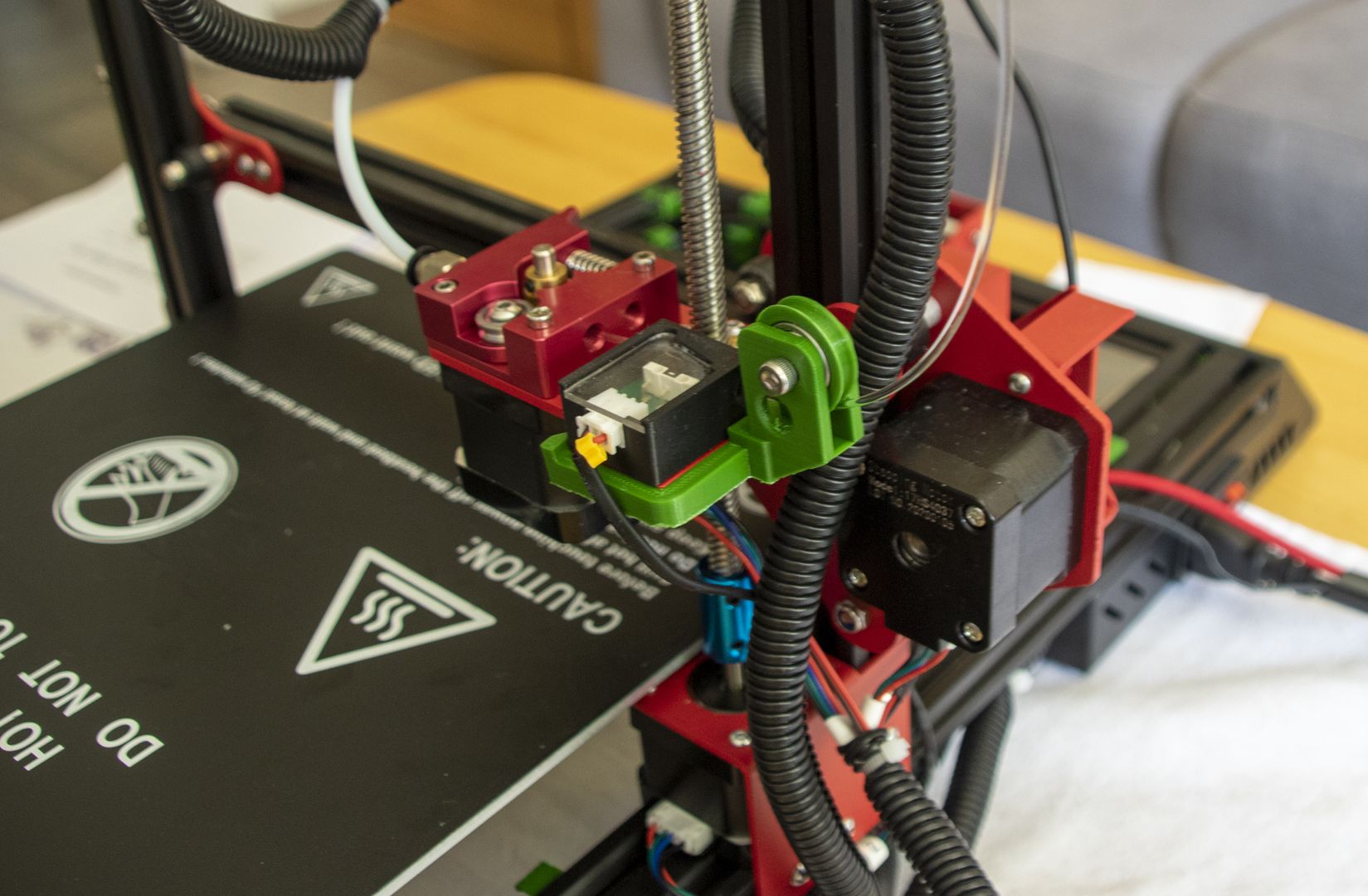
Tool Holder
The tool holder (Thingiverse) is actually intended for the Ender 3, but works just as well for the U50.
The finished part is simply put on the side of the upper crossbar.
Z-Axis Stabilizer and Filament Guide
The threaded rod of the Z-axis has no support or guide at the upper end when delivered.
I haven’t had any problems with it, because I haven’t printed very high yet, but I found this bracket on Thingiverse.
Now the threaded rod is held with a ball bearing at the top.
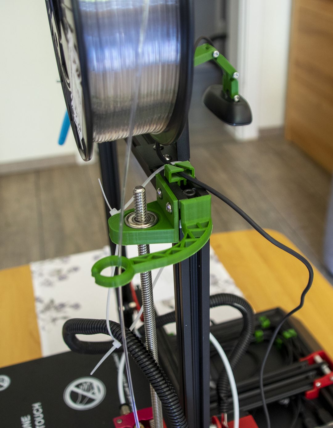
The filament guide consists of two parts. At the top I have chosen this arm (Thingiverse), which you can see on the last picture. For this I had to shorten one leg with the pliers, because it got in the way with the Z-axis mount.
At the bottom I added a guide which was constructed directly for the U50 and holds a ball bearing (Thingiverse).
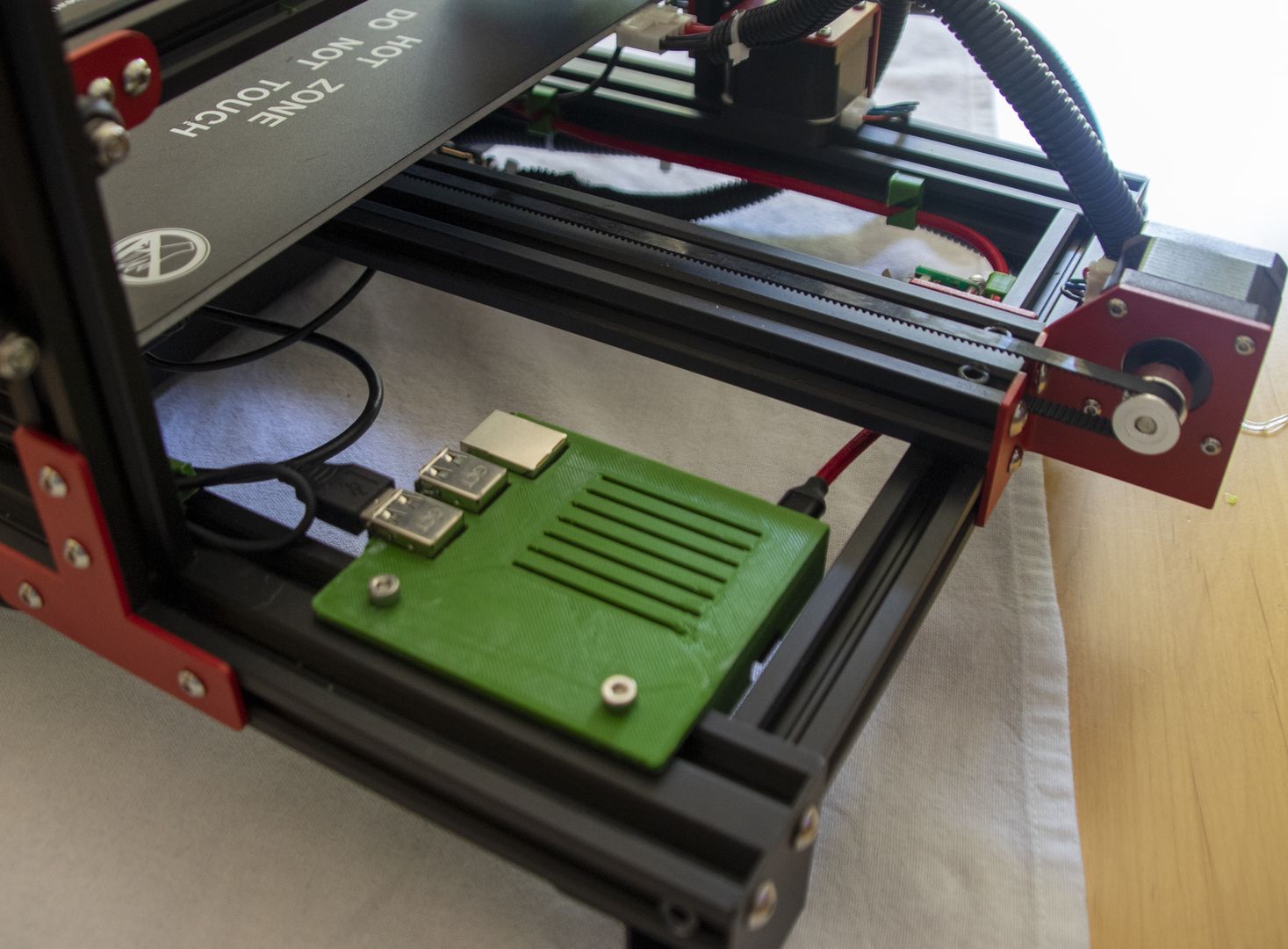
Raspberry Case
As mentioned before, I print exclusively via Octoprint, which runs on a Raspberry Pi 3.
So I printed a case that can be mounted in the frame below the printing bed (Thingiverse).
Holder for USB-Hub
In the beginning I had the webcam and printer connected directly to the Raspberry Pi. But this caused the power supply to drop out from time to time, especially during startup when the printer electronics are not yet supplied by its own power supply. Therefore I now use a USB hub with its own power supply, which is mounted between the printer electronics and the printing bed. I designed the mounting bracket for it myself in OpenSCAD.
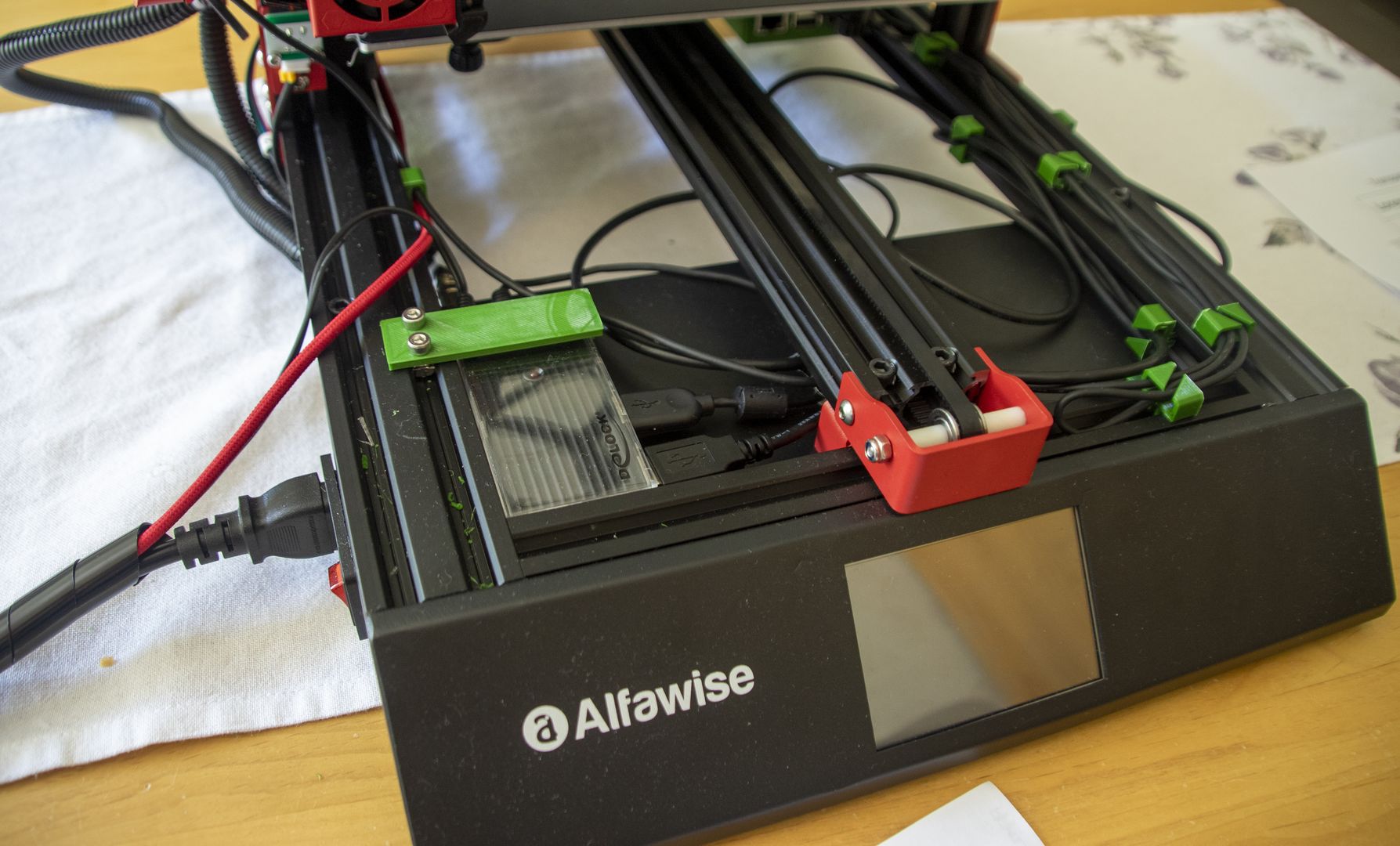
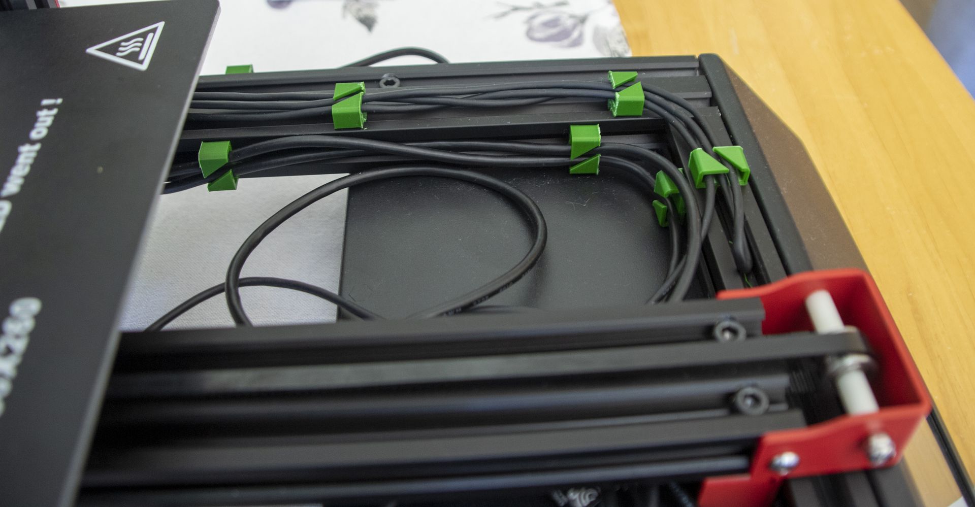
Cablemanagement
To avoid the many additional cables flying around wildly and getting tangled up with the moving parts of the printer I printed out a handful of cable guides for aluminium profiles (Thingiverse).
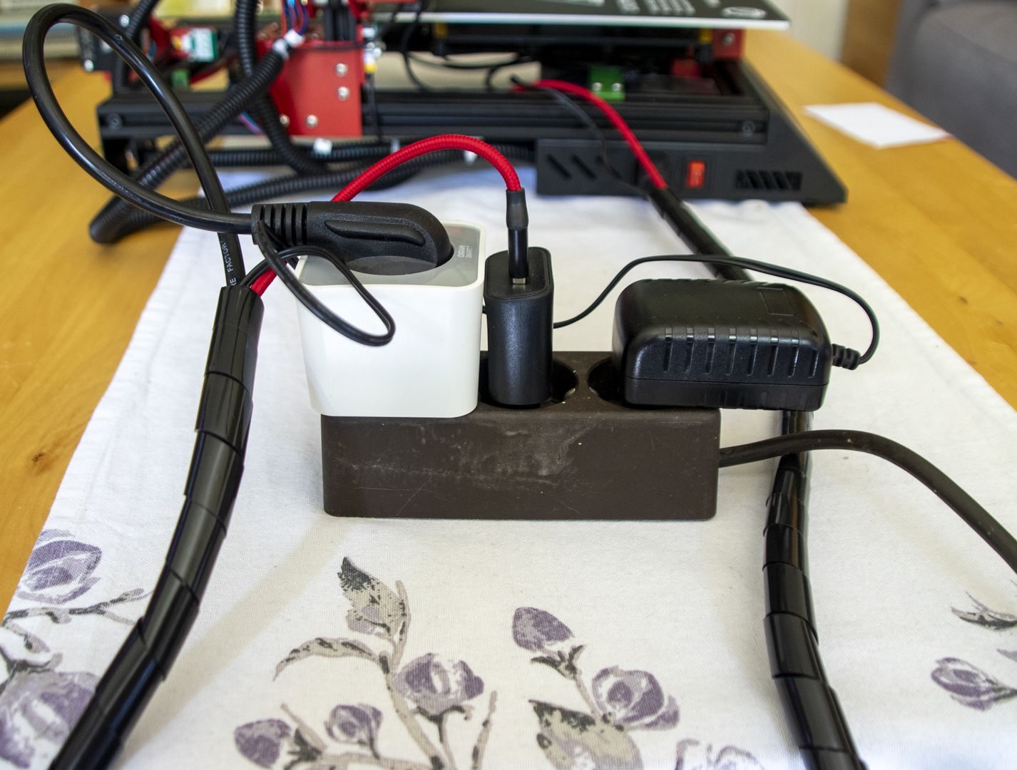
For the power supply everything is plugged into a triple socket. The three cables for the printer, the Raspberry Pi and the USB hub are bundled together with a spiral hose.
The printer plug is also plugged into an Osram Smart socket so that I can disconnect the printer from the mains if necessary.
For the connection to my Smarthome there will be a separate article.
Insights in printing
The first important thing to know is to check the leveling before each print. The printed parts stick extremely tight to the supplied printing bed, so that I sometimes have to use some force to remove them. This often changes the leveling.
The second insight is to always level with a warm printing bed. Otherwise the temperature will change the leveling again.
Translated with www.DeepL.com/Translator (free version)